 Двигатели для работы только от преобразователя
 Converter-fed operation up to 500 V +10 % line voltage
The standard insulation of the 1LA and 1LG motors is designed such that operation on the converter is possible at line voltages up to 500 V +10 % in motorized operation (for motor series 1LA8, up to 500 V +10 % generally). This also applies for operation with a pulse-controlled AC converter with voltage rise times of ts > 0.1 μs at the motor terminals (IGBT transistors). At higher voltages, the motors require increased insulation resistance. Please inquire in the case of converter-fed operation with motors with protruding connection cables (order codes L44, L45, L47, L48, L49, L51 and L52).
The 1LA8 non-standard motors of the types specially identified for converter-fed operation (the 9th and 10th position of the Order No. is filled with "PB", "PC" or "PE") have an insulated motor bearing as standard at the non-drive end NDE. The motors are equipped with standard insulation and standard rotors and are suitable for mains-fed and converter-fed operation. For further information, see Part 3 of this catalog "SIMOTICS N-compact Non-Standard Motors".
Converter-fed operation up to 690 V +10 % line voltage
1LA5, 1LA7 and 1LG6 standard motors as well as 1LA8 and 1PQ8 non-standard motors are also available with a higher insulation resistance of the winding system for operation on the converter with supply voltages from 500 to 690 V (+10 %), and do not usually require a filter. These motors are identified by an "M" in the 10th digit of the Order No. (e.g. 1LA83152PM).
With the reinforced insulating system, there is less space in the grooves in motor series 1LA8 and 1PQ8 for the same number of windings compared to the normal version, which slightly reduces the rated output of these motors. For further information, see Part 3 of this catalog "SIMOTICS N-compact Non-Standard Motors".
Note: The configuration tool SIZER for Siemens Drives is available for configuring converter-fed motors.
| Категория | Двигатели только для работы с преобразователем | |||
|---|---|---|---|---|
| Серийная версия | Алюминиевый корпус 1LA7 и 1LA5with special insulation up to 690 V | |||
| Охлаждение | Самовентилируемый (IC 411) | |||
| Степень защиты | IP55, опционально IP56 или IP65 | |||
| Класс изоляции | 155 (F) | |||
| Класс нагревостойкости | 130 (B) | |||
| Число полюсов | 2, 4, 6 | |||
| Размер корпуса (FS) | 100 L ... 225 M | |||
| Номинальная мощность при 50 Гц | 1.5 ... 45 кВт | |||
| Синхронная скорость вращения | 1000 ... 3600 об/мин | |||
| Номинальный крутящий момент при 50 Гц | 9.9 ... 293 Нм | |||
| Эффективность | Standard Efficiency | |||
| Диапазон двигателей с заказным номером для конструктивного исполнения IM B3 | ||||
|
| Prated, 50 Hz | IEclass | Размер корпуса | Заказной номер |
| кВт |
| FS |
| |
| 2-полюсный: 3000 об/мин при 50 Гц | ||||
| 3 | – | 100 L | 1LA7106‑2PM.. | |
| 4 | – | 112 M | 1LA7113‑2PM.. | |
| 5.5 | – | 132 S | 1LA7130‑2PM.. | |
| 7.5 | – | 132 S | 1LA7131‑2PM.. | |
| 11 | – | 160 M | 1LA7163‑2PM.. | |
| 15 | – | 160 M | 1LA7164‑2PM.. | |
| 18.5 | – | 160 L | 1LA7166‑2PM.. | |
| 22 | – | 180 M | 1LA5183‑2PM.. | |
| 30 | – | 200 L | 1LA5206‑2PM.. | |
| 37 | – | 200 L | 1LA5207‑2PM.. | |
| 45 | – | 225 M | 1LA5223‑2PM.. | |
| 4-полюсный: 1500 об/мин при 50 Гц | ||||
| 2.2 | – | 100 L | 1LA7106‑4PM.. | |
| 3 | – | 100 L | 1LA7107‑4PM.. | |
| 4 | – | 112 M | 1LA7113‑4PM.. | |
| 5.5 | – | 132 S | 1LA7130‑4PM.. | |
| 7.5 | – | 132 M | 1LA7133‑4PM.. | |
| 11 | – | 160 M | 1LA7163‑4PM.. | |
| 15 | – | 160 L | 1LA7166‑4PM.. | |
| 18.5 | – | 180 M | 1LA5183‑4PM.. | |
| 22 | – | 180 L | 1LA5186‑4PM.. | |
| 30 | – | 200 L | 1LA5207‑4PM.. | |
| 37 | – | 225 S | 1LA5220‑4PM.. | |
| 45 | – | 225 M | 1LA5223‑4PM.. | |
| 6-полюсный: 1000 об/мин при 50 Гц | ||||
| 1.5 | – | 100 L | 1LA7106‑6PM.. | |
| 2.2 | – | 112 M | 1LA7113‑6PM.. | |
| 3 | – | 132 S | 1LA7130‑6PM.. | |
| 4 | – | 132 M | 1LA7133‑6PM.. | |
| 5.5 | – | 132 M | 1LA7134‑6PM.. | |
| 7.5 | – | 160 M | 1LA7163‑6PM.. | |
| 11 | – | 160 L | 1LA7166‑6PM.. | |
| 15 | – | 180 L | 1LA5186‑6PM.. | |
| 18.5 | – | 200 L | 1LA5206‑6PM.. | |
| 22 | – | 200 L | 1LA5207‑6PM.. | |
| 30 | – | 225 M | 1LA5223‑6PM.. | |
Особенности
Двигатели для работы только от преобразователя Motors operating with frequency converters offer the user numerous advantages:
- The motors feature the future-oriented insulation system DURIGNIT IR 2000 (IR = Inverter Resistant). The DURIGNIT IR 2000 insulation system consists of high-quality enamel wires and insulating sheeting in conjunction with solvent-free resin impregnation.
The motors specially developed for operation on a frequency converter with special insulation are converter-compatible from 500 to 690 V (+10 %).
Область применения
Двигатели для работы только от преобразователя The motors can be used in numerous drive applications with variable-speed drives when they are combined with converters from the MICROMASTER and SINAMICS spectrum.
The wide field of implementation includes the following applications:
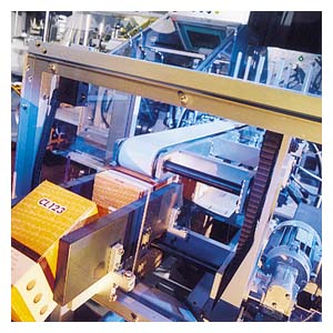
- Conveyor systems such as cranes, belts and lifting gear
- High-bay warehouses
- Packaging machines
- Automation and drives
Their large range of line voltages enables them to be used all over the world.
Технические данные
Двигатели для работы только от преобразователя General note
All the data listed in the catalog is applicable for a 50 Hz line supply. With converter-fed operation, the torque reduction factors for constant torque and drives for fans, pumps and compressors must be configured using SIZER for Siemens Drives. Higher noise levels must be expected at frequencies other than 50 Hz for motors operating with converters due to the harmonic content of the supply.
Rated voltage
The tolerance of the motors specially developed for converterfed operation with special insulation up to 690 V (the 9th and 10th position of the Order No. are marked with "PM") is generally in accordance with DIN EN 60034-1 – a rated voltage range is not specified on the rating plate.
Mechanical limit speeds
When the motor is operated at its rated frequency, it is important to note that the maximum speeds are limited by the limits for the roller bearings, critical rotor speed and rigidity of the rotating parts.
Motor protection
A motor protection function can be implemented using the I2t sensing circuit implemented in the converter software. If required, more precise motor protection can be afforded by direct temperature measurement using KTY-84 sensors or PTC thermistors in the motor winding. Some converters from Siemens determine the motor temperature using the resistance of the temperature sensor. They can be set to a required temperature for alarm and tripping.
Insulation
The insulation of the 1LA and 1LG motors is designed such that operation on the converter is possible at voltages up to 500 V +10 % in motorized operation (for motor series 1LA8, up to 500 V +10 % generally). This also applies for operation with a pulsecontrolled AC converter with voltage rise times ts > 0.1 μs at the motor terminals.
All motors with voltage codes 1 and 6 (400 V motors Δ connection) operating with a converter must be operated under these conditions. This does not apply to motors with voltages from 500 to 690 V (+10 %), that must have special insulation for operation on a pulse-controlled AC converter (e.g. SIMOVERT MASTERDRIVES and MICROMASTER 440 for voltages in the range from 500 to 600 V), i.e. when 10th position of the Order No. = "M". For converter-fed operation with the outputs specified in the catalog, the motors are used according to temperature class 155 (F), i.e. in this case neither a service factor > 1 nor an increased coolant temperature is possible (order codes C11, C12 and C13 cannot be ordered).
Motor connection
When connecting the motors, it is important to consider the restrictions for mains-fed machines as well as the maximum admissible conductor cross-sections for the converter.
Ventilation and noise generation
The fan noise can increase at speeds that are higher than the rated speed of self-ventilated motors. To increase motor utilization at low speeds it is recommended that forced-ventilated motors are used.
Mechanical stress and grease lifetime
High speeds that exceed the rated speed and the resulting increased vibrations alter the mechanical running smoothness and the bearings are subjected to increased mechanical stress. This reduces the grease lifetime and the bearing lifetime. More detailed information on request.
Mechanical limit speeds nmax at maximum supply frequency fmax
Standard values
The values in the following table are valid for all areas of application with the exception of "SIMOTICS XP 1MA/1MJ/1LA/1LG Explosion-Proof Motors".
The values for motor series 1LA8, 1PQ8 and 1LL8 are listed in the selection and ordering data in "SIMOTICS N-compact Non-Standard Motors".
| Motor frame size | Motor type | 2-pole 1)nmaxrpm | f max Hz | 4-polenmaxrpm | f max Hz | 6-polenmaxrpm | f max Hz | 8-polenmaxrpm | f max Hz | |
|---|---|---|---|---|---|---|---|---|---|---|
| 1LA5, 1LA6, 1LA7, 1LA9, 1LP5, 1LP7, 1PP5, 1PP7 | ||||||||||
| 63 M | 1LA7/1LA91LP7/1PP7 | 06. | 6000 | 100 | 4200 | 140 | 3600 | 180 | 3000 | 200 |
| 71 M | 1LA7/1LA91LP7/1PP7 | 07. | 6000 | 100 | 4200 | 140 | 3600 | 180 | 3000 | 200 |
| 80 M | 1LA7/1LA91LP7/1PP7 | 08. | 6000 | 100 | 4200 | 140 | 3600 | 180 | 3000 | 200 |
| 90 L | 1LA7/1LA91LP7/1PP7 | 09. | 6000 | 100 | 4200 | 140 | 3600 | 180 | 3000 | 200 |
| 100 L | 1LA6/1LA7/1LA91LP7/1PP7/1PP6 | 10. | 6000 | 100 | 4200 | 140 | 3600 | 180 | 3000 | 200 |
| 112 M | 1LA6/1LA7/1LA91LP7/1PP7/1PP6 | 11. | 6000 | 100 | 4200 | 140 | 3600 | 180 | 3000 | 200 |
| 132 S/M | 1LA6/1LA7/1LA91LP7/1PP7/1PP6 | 13. | 5600 | 90 | 4200 | 140 | 3600 | 180 | 3000 | 200 |
| 160 M/L | 1LA6/1LA7/1LA91LP7/1PP7/1PP6 | 16. | 4800 | 80 | 4200 | 140 | 3600 | 180 | 3000 | 200 |
| 180 M/L | 1LA5/1LA91LP5/1PP5 | 18. | 5100 | 85 | 4200 | 140 | 3600 | 180 | 3000 | 200 |
| 200 L | 1LA5/1LA9 1LP5/1PP5 | 20. | 5100 | 85 | 4200 | 140 | 3600 | 180 | 3000 | 200 |
| 225 S/M | 1LA5 | 22. | 5100 | 85 | 4200 | 140 | 3600 | 180 | 3000 | 200 |
| 1LG4, 1LG6, 1LP4, 1PP4, 1PP6 | ||||||||||
| 180 M/L | 1LG4/1LG6 1LP4/1PP4/1PP6 | 18. | 4600 | 76 | 4200 | 140 | 3600 | 180 | 3000 | 200 |
| 200 L | 1LG4/1LG6 1LP4/1PP4/1PP6 | 20. | 4500 | 75 | 4200 | 140 | 3600 | 180 | 3000 | 200 |
| 225 S/M | 1LG4/1LG6 1LP4/1PP4/1PP6 | 22. | 4500 | 75 | 4500 | 150 | 4400 | 220 | 4400 | 293 |
| 250 M | 1LG4/1LG6 1LP4/1PP4/1PP6 | 25. | 3900 | 65 | 3700 | 123 | 3700 | 185 | 3700 | 247 |
| 280 S/M | 1LG4/1LG6 1LP4/1PP4/1PP6 | 28. | 3600 | 60 | 3000 | 100 | 3000 | 150 | 3000 | 200 |
| 315 S | 1LG4/1LG6 1LP4/1PP4/1PP6 | 310 | 3600 | 60 | 2600 | 87 | 2600 | 130 | 2600 | 176 |
| 315 M | 1LG4/1LG6 1LP4/1PP4/1PP6 | 313 | 3600 | 60 | 2600 | 87 | 2600 | 130 | 2600 | 173 |
| 315 L | 1LG4/1LG6 1LP4/1PP4/1PP6 | 316317318312 | 3600 | 60 | 2600 | 87 | 2600 | 130 | 2600 | 173 |
1) Request required for continuous duty in the fmax (nmax) range.
Note:
For 1LE1 motors, see Catalog D 81.1 · 2008.
Bearings and bearing currents
When operating multiphase induction machines on a converter, an electrical bearing stress results from a capacitive induced voltage via the bearing lubricating film, depending on the principle being used. The physical cause of this is the common-mode voltage at the converter output. The sum of the three phase voltages is not zero at all times, unlike with direct on-line operation. The high-frequency, pulse-shaped common-mode voltage brings about a residual current, which closes back to the converter's DC link via the machine's internal capacitances, the machine housing and the grounding circuit. The machine's internal capacitances include the main insulation winding capacitance, the geometric capacitance between the rotor and stator, the lubricating film capacitance, and the capacitance of any bearing insulation that may be present. The current level via the internal capacitances is proportional to the common-mode voltage regulation. (i(t) = C · du/dt).
In order to apply currents to the motor which are sinusoidal as far as possible (smooth running, oscillation torques, stray losses), a high pulse frequency is required for the converter's output voltage. The related (very steep) switching edges of the converter output voltage (and also, therefore, of the common-mode voltage) cause correspondingly high capacitive currents and voltages on the machine's internal capacitances.
In the worst-case scenario, the capacitive voltage induced via the bearing can lead to random punctures of the bearing lubricating film, thus damaging the bearing/causing premature wear. The current pulses caused by the puncture in the lubricating film are referred to as EDM (Electrostatic Discharge Machining) currents, although this is not primarily a question of an electrostatic effect, but more of (partial) punctures of insulating material, i.e., of partial discharges.
This physical effect, which occurs in isolated cases, has mostly been observed in connection with larger motors.
EMC-compliant installation of the drive system is a basic prerequisite for preventing premature bearing damage via bearing currents.
The most important measures for reducing bearing currents:
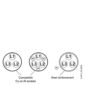
- Insulated motor bearings at the non-drive end NDEThe insulated bearing is standard for all non-standard 1LA8 motors designated for converter operation. Furthermore it is recommended that an insulated bearing is ordered for NDE as special version for motor series 1LG, 1PP4, 1LP4 and 1MJ7 frame size 225 and above (order code L27)
- Hybrid bearings with ceramic bearing elements at the drive end DE and non-drive-end NDE
- Grounding brush for converter-fed operation for 1LG motors (order code M44)
- Use of cables with a symmetrical cable cross-section:
- Use of motor reactors
- Use of grounding cables with low impedance in a large frequency range (0 Hz up to approximately 70 MHz): for example, plaited copper ribbon cables, HF litz wires
- Separate HF equipotential-bonding cable between motor housing and driven machine
- Separate HF equipotential-bonding cable between motor housing and converter PE busbar
- 360° HF contacting of the cable shield on the motor housing and the converter PE busbar. This can be achieved using EMC screwed glands on the motor end and EMC shield clips on the converter end, for example.
Common-mode filters at the converter output (e.g. nanoperm rings) These measures may be necessary depending on the application in converter-fed operation for motor series 1LA5 frame size 225 and 1LG frame size 225 and above, and are therefore recommended.
Motor protection
KTY 84-130 temperature sensor
Order codesA23: 1 x KTY 84-130A25: 2 x KTY 84-130
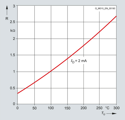
This semiconductor sensor changes its resistance as a function of the temperature in accordance with a defined curve.
KTY 84-130 temperature sensor
For 1LA8 motors, the PTC thermistors supplied as standard are omitted when ordering with order code A23.
For mains-fed operation, the temperature monitoring device 3RS10 that is part of the protection equipment can be ordered separately. For further details, see Catalog C 10.
Bearings
For converter-fed operation with frame size 225 and above, it is recommended that an "Insulated bearing cartridge" – Order code L27 is used.
Ventilation/noise generation
The fan noise can increase at speeds that are higher than the rated speed of self-ventilated motors.
To increase motor utilization at low speeds, it is recommended that forced-ventilated motors are used, in particular motor series 1LA5, 1LA7, 1LG4 and 1LG6 with order code G17 or motor series 1PQ8.
Insulation
For converter-fed operation with the outputs specified in the catalog, the motors are used according to temperature class 155 (F), i.e. in this case neither a service factor > 1 nor an increased coolant temperature is possible, i.e. order codes C11, C12 and C13 cannot be ordered. Explosion-proof motors for Zones 2, 21 and 22 are used in accordance with temperature class 130 (B).
Supply frequencies higher than 60 Hz
For converter-fed operation with frequencies higher than 60 Hz, special balancing is required for compliance with the specified limit values (plain text: Max. speed).
ECOFAST motor connectors
In combination with the ECOFAST versions for distributed drive solutions, the following motor connectors can be ordered separately:
- ECOFAST motor connector, standard (unshielded connection): Order code G55
- ECOFAST motor connector, EMC (shielded connection):Order code G56 Shielded motor connection cables must be used for frequency converters and soft starters.
Maximum admissible line voltage on motor connector: ≤ 500 V
Ordering example:
| Selection criteria | Requirement | Structure of the Order No. |
|---|---|---|
| Motor type | Standard motor with high efficiency (IE2), IP55 degree of protection, aluminum housing | 1LA9■■■-■■■■■ |
| No. of poles/ speed | 4-pole/1500 rpm | 1LA9090-4KA90 L1U |
| Rated output | 1.1 kW | |
| Special voltage and frequency | Star-delta starting for a line voltage 400 VΔ, 50 Hz 1) | |
| Type of construction | IM B3 | |
| ECOFAST connector | Shielded connection | 1LA9090-4KA90-Z L1U + G56 |
1) Note: Voltage code 9 with order code L1U must be selected due to the 400 V voltage. With voltage code 6 (= 400 VΔ/690 VY, 50 Hz), temporary voltage peaks of 690 V can arise which can cause faults on the ECOFAST connectors.
Grounding brushes for converter-fed operation
Grounding brushes are available for converter-fed operation for 1LG4 and 1LG6 motors with order code M44. Please contact your local Siemens office for advice.