| | 6ES7 431-0HH00-0AB0 | 6ES7 431-1KF20-0AB0 | 6ES7 431-1KF00-0AB0 | 6ES7 431-1KF10-0AB0 |
| Voltages and currents | | | | |
| Load voltage L+ | | | | |
| | 24 V; only required for supplying 2-wire transmitters | 24 V; only required for supplying 2-wire transmitters | | 24 V; only required for supplying 2-wire transmitters |
- reverse polarity protection
| Yes | Yes | | Yes |
| Current consumption | | | | |
| from load voltage L+ (without load), max. | 400 mA; for 16 connected, fully controlled 2-wire transmitters | 200 mA; for 8 connected, fully controlled 2-wire transmitters | | 200 mA |
| from backplane bus DC 5 V, max. | 100 mA | 1,000 mA | 350 mA | 600 mA |
| Power loss, typ. | 2 W | 4.9 W | 1.8 W | 3.5 W |
| Analog inputs | | | | |
| Number of analog inputs | 16 | 8 | 8 | 8 |
| Number of analog inputs for voltage/current measurement | 16 | 8 | 8 | 8 |
| Number of analog inputs for resistance measurement | | 4 | 4 | 4 |
| cable length, shielded, max. | 200 m | 200 m | 200 m | 200 m; 50 m with thermocouples and input ranges <= 80 mV |
| permissible input frequency for voltage input (destruction limit), max. | 20 V; 20 V continuous, 75 V for max. 1 s (mark to space ratio 1:20) | 18 V; 18 V continuous, 75 V for 1 ms (mark to space ratio 1:20) | 50 V | 18 V; 18 V continuous, 75 V for 1 ms (mark to space ratio 1:20) |
| permissible input current for current input (destruction limit), max. | 40 mA | 40 mA; Permanent | 50 mA; 40 mA continuous | 40 mA; Permanent |
| Input ranges (rated values), voltages | | | | |
| | Yes | Yes | Yes | Yes |
| | Yes | Yes | Yes | Yes |
| | Yes | Yes | Yes | Yes |
| | | | | Yes |
| | | | | Yes |
| | | | | Yes |
| | | | | Yes |
| | | | | Yes |
| Input ranges (rated values), currents | | | | |
| | | | | Yes |
| | Yes | Yes | Yes | |
| | Yes | Yes | Yes | Yes |
| Input ranges (rated values), thermoelements | | | | |
| | | | | Yes |
| | | | | Yes |
| | | | | Yes |
| | | | | Yes |
| | | | | Yes |
| | | | | Yes |
| | | | | Yes |
| | | | | Yes |
| | | | | Yes |
| | | | | Yes |
| Input ranges (rated values), resistors | | | | |
| | | | | Yes |
| | | | | Yes |
| | | | | Yes |
| | | Yes | Yes | Yes |
| | | | | Yes; usable up to 5000 ohms |
| Input ranges (rated values), resistance thermometers | | | | |
| | | | | Yes |
| | | | | Yes |
| | | | | Yes |
| | | | | Yes |
| | | | | Yes |
| | | | | Yes |
| | | | | Yes |
| Characteristic curve linearization | | | | |
| | | | | Yes |
| | | | | Type B, E, J, K, L, N, R, S, T, U |
| | | | | Pt100, Pt200, Pt500, Pt1000, Ni100, Ni1000 |
| Temperature compensation | | | | |
- external temperature compensation with compensations socket
| | | | Yes |
- external temperature compensation with Pt100
| | | | Yes |
- internal temperature compensation
| | | | No |
- dynamic reference temperature value
| | | | Yes |
| Analog value creation | | | | |
| Integration and conversion time/resolution per channel | | | | |
- Resolution with overload area (bit including sign), max.
| 13 Bit | 14 Bit; 14 / 14 / 14 | 13 Bit | 14 Bit; with activated smoothing: 16 Bit |
- Integration time, parameterizable
| Yes | Yes | Yes | Yes |
| | 50 / 60 ms | | 16.7 / 20 ms | 16.7 / 20 ms |
- Basic conversion time, ms
| 55 / 65 ms | 52 µs | 23 / 25 ms | 20.1 / 23.5 ms |
- additional conversion time for wire break monitoring
| | | | 4.3 ms |
- additional conversiontime for wire break monitoring and resistance measurement
| | | | 5.5 ms |
- additional conversiontime for resistance measurement
| | | | 40.2 / 47 ms |
- Interference voltage suppression for interference frequency f1 in Hz
| 60 / 50 Hz | none / 400 / 60 / 50 Hz | 60 / 50 Hz | 60 / 50 Hz |
| Encoder | | | | |
| Connection of signal encoders | | | | |
- for current measurement as 2-wire transducer
| | Yes | Yes; with external transmitter supply | Yes |
- for current measurement as 4-wire transducer
| Yes | Yes | Yes | Yes |
- for resistance measurement with 2-conductor connection
| | Yes; Line resistances are also measured | Yes; Line resistances are also measured | Yes; Line resistances are also measured |
- for resistance measurement with 3-conductor connection
| | Yes; Line resistances are also measured | Yes; Line resistances are also measured | Yes |
- for resistance measurement with 4-conductor connection
| | Yes | Yes | Yes |
| Errors/accuracies | | | | |
| Operational limit in overall temperature range | | | | |
- Voltage, relative to input area
| +/- 0,65 %; 1.0% at 1 to 5 V; 0.65% at +/-1 V, +/-10 V | +/- 0,7 %; +/-0.7% at +/-1 V; +/-0.9% at +/-10 V, 1 to 5 V | +/- 1 %; +/-1.0% at +/-1 V; +/-0.6% at +/-10 V; +/-0.7% at 1 to 5 V | +/- 0,38 %; +/-0.38% at +/-80 mV; +/-0.35% at +/-250 mV, +/-500mV, +/-1 V, +/-2,5 V, +/-5 V, 1 to 5 V, +/-10 V |
- Current, relative to input area
| +/- 0,65 % | +/- 0,8 %; at +/-20 mA, 4 to 20 mA | +/- 1 %; at +/-20 mA, 4 to 20 mA | +/- 0,35 %; 0 to 20 mA, +/-20 mA, 4 to 20 mA |
- Impedance, relative to input area
| | +/- 1 % | +/- 1,25 %; 0 to 500 ohms (4-conductor measurement, in range of 600 ohms) | +/- 0,5 % |
- Resistance-type thermometer, relative to input area
| | | | +/- 0,5 % |
| Basic error limit (operational limit at 25 °C) | | | | |
- Voltage, relative to input area
| +/- 0,25 %; 0.5% at 1 to 5 V; 0.25% at +/-1 V, +/-10 V | +/- 0,6 %; 0.6% at +/-1 V; 0.75% at +/-10 V, 1 to 5 V | +/- 0,7 %; 0.7% at +/-1 V; 0.4% at +/-10 V; 0.5% at 1 to 5 V | +/- 0,15 %; +/-0.15% (+/-250 mV, +/-500 mV, +/-1 V, +/-2.5 V, +/-5 V, 1 to 5 V, +/- 10 V); +/-0.17% (+/- 80 mV); |
- Current, relative to input area
| +/- 0,25 %; at +/-20 mA, 4 to 20 mA | +/- 0,7 %; at +/- 20 mA, 4...20 mA | +/- 0,7 %; at +/- 20 mA, 4...20 mA | +/- 0,15 %; 0 to 20 mA, +/- 20 mA, 4 to 20 mA |
- Impedance, relative to input area
| | +/- 0,7 %; 0 to 600 ohms | +/- 0,8 %; 0 to 500 ohms (4-conductor measurement, in range of 600 ohms) | +/- 0,15 %; +/-0.15% at 0 to 48 ohms (4-conductor measurement), 0 to 150 ohms (4-conductor measurement), 0 to 300 ohms (4-conductor measurement), 0 to 600 ohms (4-conductor measurement), 0 to 5000 ohms (4-conductor measurement, in range of 6000 ohms); +/-0.3% at 0 to 300 ohms (3-conductor measurement), 0 to 600 ohms (3-conductor measurement), 0 to 5000 ohms (3-conductor measurement, in range of 6000 ohms) |
- Resistance-type thermometer, relative to input area
| | | | +/- 0,3 % |
| Isolation | | | | |
| Isolation checked with | 500 V DC between bus and local ground | 2120 V DC between bus and analog part; 500 V DC between bus and local ground; 707 V DC between analog part and L+/M; 2120 V DC between analog part and local ground; 2120 V DC between L+/M and local ground | 2120 V DC between bus and analog part; 500 V DC between bus and local ground; 2120 V DC between analog part and local ground | 2120 V DC between bus and L+/M; 2120 V D between bus and analog part; 500 V DC between bus and local ground; 707 V DC between analog part and L+/M; 2120 V DC between analog part and local ground; 2120 V DC between L+/M and local ground |
| Isolation | | | | |
| Isolation, analog inputs | | | | |
| | No | Yes; internal/external | Yes; internal/external | Yes; internal/external |
| | No | No | No | No |
| Permissible potential difference | | | | |
| between the inputs (UCM) | 2 V DC / 2 Vpp AC | 8 V AC | 30 V AC | 120 V AC |
| Dimensions | | | | |
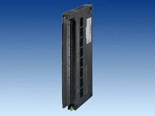
| Width | 25 mm | 25 mm | 25 mm | 25 mm |
| Height | 290 mm | 290 mm | 290 mm | 290 mm |
| Depth | 210 mm | 210 mm | 210 mm | 210 mm |
| Dimensions | | | | |
| Required slots | 1 | 1 | 1 | 1 |
| Weights | | | | |
| Weight, approx. | 500 g | 500 g | 500 g | 500 g |