Общее - ULTRAMAT 6
 The ULTRAMAT 6 single-channel or dual-channel gas analyzers operate according to the NDIR two-beam alternating light principle and measure gases highly selectively whose absorption bands lie in the infrared wavelength range from 2 to 9 μm, such as CO, CO2, NO, SO2, NH3, H2O as well as CH4 and other hydrocarbons. Single-channel analyzers measure up to 2 gas components, dual-channel analyzers up to 4 gas components simultaneously.
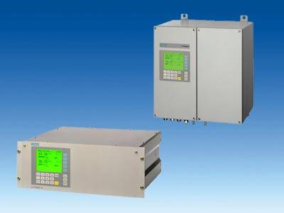 ULTRAMAT 6, 19“ unit and field unit | |||||||||||||||||||||||||||||||||||||||||||||||||||||||||||||||||||||||||||||||||||||||||||||||||||||||||||||||||||||||||||||||||||||||||||||||||||||||||||||||||||||||||||||||||||
Особенности
| |||||||||||||||||||||||||||||||||||||||||||||||||||||||||||||||||||||||||||||||||||||||||||||||||||||||||||||||||||||||||||||||||||||||||||||||||||||||||||||||||||||||||||||||||||
Область примененияApplication
Special versions
Furthermore, the TÜV-approved versions of the ULTRAMAT 6 comply with the requirements of EN 14956 and of QAL 1 according to EN 14181. Conformity of the analyzers with both standards is TÜV-certified. Determination of the analyzer drift according to EN 14181 (QAL 3) can be carried out manually or also with a PC using the SIPROM GA maintenance and servicing software. In addition, selected manufacturers of emission evaluation computers offer the possibility for downloading the drift data via the analyzer’s serial interface and to automatically record and process them in the evaluation computer.
| |||||||||||||||||||||||||||||||||||||||||||||||||||||||||||||||||||||||||||||||||||||||||||||||||||||||||||||||||||||||||||||||||||||||||||||||||||||||||||||||||||||||||||||||||||
Дизайн19“ unit
Field unit
Display and control panel
Inputs and outputs
Communication
Options
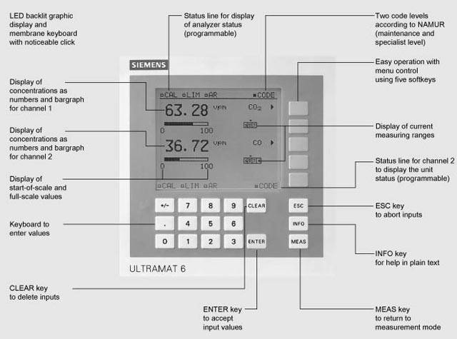 ULTRAMAT 6, membrane keyboard and graphic display Versions – Wetted parts, standard
Options
Versions – Wetted parts, special applications (examples)
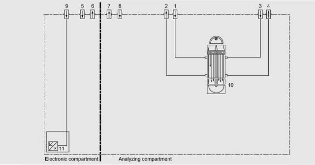
Gas path (19“ unit)
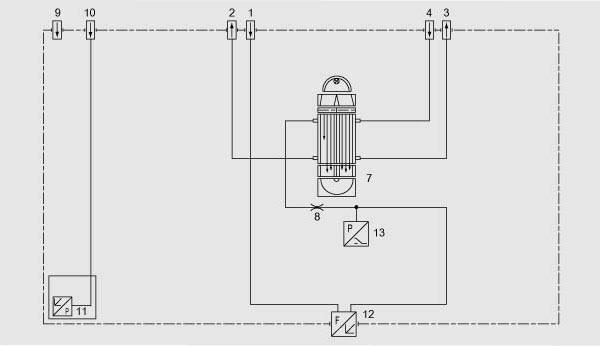 Gas path ULTRAMAT 6, single-channel unit, 19“ unit, with flow-type reference cell (option) 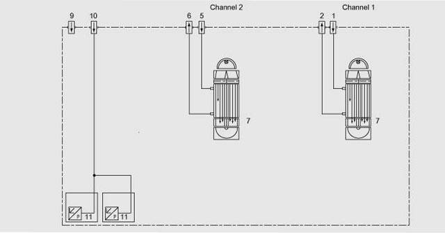 Gas path ULTRAMAT 6, dual-channel unit, 19“ unit Gas path (field unit)
 Gas path ULTRAMAT 6, field unit, with flow-type reference cell (option)
| |||||||||||||||||||||||||||||||||||||||||||||||||||||||||||||||||||||||||||||||||||||||||||||||||||||||||||||||||||||||||||||||||||||||||||||||||||||||||||||||||||||||||||||||||||
ФункцииMode of operationThe ULTRAMAT 6 gas analyzer operates according to the infrared two-beam alternating light principle with double-layer detector and optical coupler. The measuring principle is based on the molecule-specific absorption of bands of infrared radiation. The absorbed wavelengths are characteristic to the individual gases, but may partially overlap. This results in cross-sensitivities which are reduced to a minimum in the ULTRAMAT 6 gas analyzers by the following measures:
The figure shows the measuring principle. An IR source (1) which is heated to approx. 700 ºC and which can be shifted to balance the system is divided by the beam divider (3) into two equal beams (sample and reference beams). The beam divider also acts as a filter cell. The reference beam passes through a reference cell (8) filled with N2 (a non-infrared-active gas) and reaches the right-hand side of the detector (11) practically unattenuated. The sample beam passes through the sample cell (7) through which the sample gas flows and reaches the left-hand side of the detector (10) attenuated to a lesser or greater extent depending on the concentration of the sample gas. The detector is filled with a defined concentration of the gas component to be measured. The detector is designed as a double-layer detector. The center of the absorption band is preferentially absorbed in the upper detector layer, the edges of the band are absorbed to approximately the same extent in the upper and lower layers. The upper and lower detector layers are connected together via the microflow sensor (12). This coupling means that the spectral sensitivity has a very narrow band. The optical coupler (13) lengthens the lower receiver cell layer optically. The infrared absorption in the second detector layer is varied by changing the slider position (14). It is thus possible to individually minimize the influence of interfering components. A chopper (5) rotates between the beam divider and the sample cell and interrupts the two beams alternately and periodically. If absorption takes place in the sample cell, a pulsating flow is generated between the two detector levels which is converted by the microflow sensor (12) into an electric signal. The microflow sensor consists of two nickel grids heated to approx. 120 °C which, together with two further resistors, form a Wheatstone bridge. The pulsating flow together with the very close arrangement of the Ni grids leads to a change in resistance. This leads to an offset in the bridge which is dependent on the concentration of the sample gas. Notes The sample gases have to enter the analyzer dustfree. Avoid condensate in the sample cells. Therefore an appropriate gas preparation is required in most applications. The ambient air of the analyzer should be, in a large extent, free of high concentration of the component to be measured. Flow-type reference sides with reduced flow must not be used with flammable or toxic gases. Channels with electronically suppressed zero only differ from the standard version by the measuring ranges parameterization. Physically suppressed zeros are implemented as special applications. 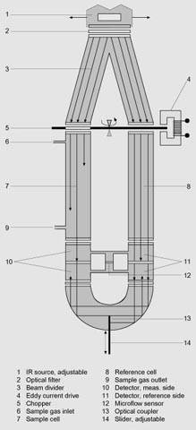 ULTRAMAT 6, mode of operation Essential characteristics
Additional characteristics, dual-channel version
| |||||||||||||||||||||||||||||||||||||||||||||||||||||||||||||||||||||||||||||||||||||||||||||||||||||||||||||||||||||||||||||||||||||||||||||||||||||||||||||||||||||||||||||||||||