Общее - ULTRAMAT/OXYMAT 6
 The ULTRAMAT/OXYMAT 6 gas analyzer is a practical combination of the ULTRAMAT 6 and OXYMAT 6 analyzers in a single enclosure. The ULTRAMAT 6 channel operates according to the NDIR two-beam alternating light principle and measures one or two gases highly selectively whose absorption bands lie in the infrared wavelength range from 2 to 9 μm, such as CO, CO2, NO, SO2, NH3, H2O as well as CH4 and other hydrocarbons. The OXYMAT 6 channel is based on the paramagnetic alternating pressure method and is used to measure oxygen in gases. 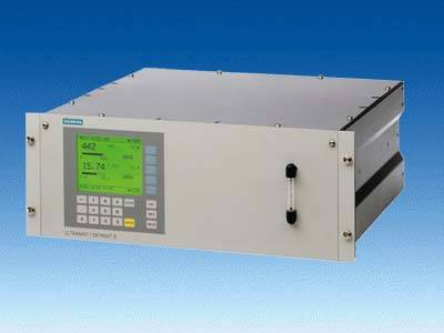 ULTRAMAT/OXYMAT 6, 19“ unit | |||||||||||||||||||||||||||||||||||||||||||||||||||||||||||||||||||||||||||||||||||||||||||||||||||||||||||||||||||||||||||||||||||||||||
Особенности
ULTRAMAT channel
OXYMAT channel
| |||||||||||||||||||||||||||||||||||||||||||||||||||||||||||||||||||||||||||||||||||||||||||||||||||||||||||||||||||||||||||||||||||||||||
Область примененияApplications
Special versions
All larger measuring ranges are also permitted. Furthermore, the TÜV-approved versions of the ULTRAMAT/OXYMAT 6 comply with the requirements of EN 14956 and of QAL 1 according to EN 14181. Conformity of the analyzers with both standards is TÜV-certified. Determination of the analyzer drift according to EN 14181 (QAL 3) can be carried out manually or also with a PC using the SIPROM GA maintenance and servicing software. In addition, selected manufacturers of emission evaluation computers offer the possibility for downloading the drift data via the analyzer’s serial interface and to automatically record and process them in the evaluation computer.
| |||||||||||||||||||||||||||||||||||||||||||||||||||||||||||||||||||||||||||||||||||||||||||||||||||||||||||||||||||||||||||||||||||||||||
Дизайн19“ unit
Display and control panel
Inputs and outputs (per channel)
CommunicationRS 485 present in the basic unit (connection at the rear and for the 19” unit also behind the front plate). Options
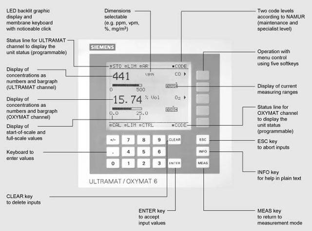 ULTRAMAT/OXYMAT 6, membrane keyboard and graphic display Versions – Wetted parts, standard
Options
Versions – Wetted parts, special applications (examples)
Versions – Wetted parts, standard
Options
Gas path
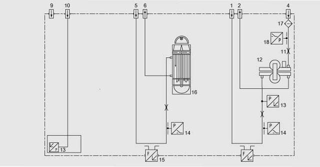 ULTRAMAT/OXYMAT 6, gas path (example) IR channel without flow-type reference side 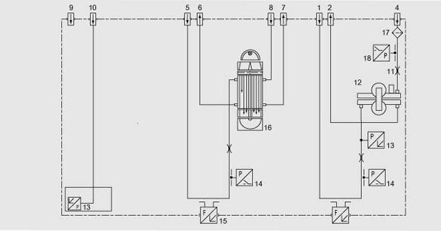 ULTRAMAT/OXYMAT 6, gas path (example) IR channel with flow-type reference side
| |||||||||||||||||||||||||||||||||||||||||||||||||||||||||||||||||||||||||||||||||||||||||||||||||||||||||||||||||||||||||||||||||||||||||
ФункцииMode of operation, ULTRAMAT channelThe ULTRAMAT channel operates according to the infrared two-beam alternating light principle with double-layer detector and optical coupler. The measuring principle is based on the molecule-specific absorption of bands of infrared radiation. The absorbed wavelengths are characteristic to the individual gases, but may partially overlap. This results in cross-sensitivities which are reduced to a minimum in the ULTRAMAT 6 gas analyzers by the following measures:
The figure shows the measuring principle. An IR source (1) which is heated to approx. 700 ºC and which can be shifted to balance the system is divided by the beam divider (3) into two equal beams (sample and reference beams). The beam divider also acts as a filter cell. The reference beam passes through a reference cell (8) filled with N2 (a non-infrared-active gas) and reaches the right-hand side of the detector (11) practically unattenuated. The sample beam passes through the sample cell (7) through which the sample gas flows and reaches the left-hand side of the detector (10) attenuated to a lesser or greater extent depending on the concentration of the sample gas. The detector is filled with a defined concentration of the gas component to be measured. The detector is designed as a double-layer detector. The center of the absorption band is preferentially absorbed in the upper detector layer, the edges of the band are absorbed to approximately the same extent in the upper and lower layers. The upper and lower detector layers are connected together via the microflow sensor (12). This coupling means that the spectral sensitivity has a very narrow band. The optical coupler (13) lengthens the lower receiver cell layer optically. The infrared absorption in the second detector layer is varied by changing the slider position (14). It is thus possible to individually minimize the influence of interfering components. A chopper (5) rotates between the beam divider and the sample cell and interrupts the two beams alternately and periodically. If absorption takes place in the sample cell, a pulsating flow is generated between the two detector levels which is converted by the microflow sensor (12) into an electric signal. The microflow sensor consists of two nickel grids heated to approx. 120 °C which, together with two further resistors, form a Wheatstone bridge. The pulsating flow together with the very close arrangement of the Ni grids leads to a change in resistance. This leads to an offset in the bridge which is dependent on the concentration of the sample gas. Notes The sample gases have to enter the analyzer dustfree. Avoid condensate in the sample cells. Therefore an appropriate gas preparation is required for most applications. The ambient air of the analyzer should be, in a large extent, free of high concentration of the component to be measured. Flow-type reference sides with reduced flow must not be operated with flammable or toxic gases. Channels with electronically suppressed zero only differ from the standard version in the measuring range parameterizing. Physically suppressed zeros are carried out as special application. 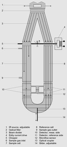 ULTRAMAT 6, mode of operation Mode of operation, OXYMAT channelIn contrast to almost all other gases, oxygen is paramagnetic. This property is utilized as the measuring principle by the OXYMAT channel. Oxygen molecules in an inhomogeneous magnetic field are drawn in the direction of increased field strength due to their paramagnetism. When two gases with different oxygen concentrations meet in a magnetic field, a pressure difference is produced between them. One gas (1) is a reference gas (N2, O2 or air), the other is the sample gas (5). The reference gas is introduced into the sample cell (6) through two channels (3). One of these reference gas streams meets the sample gas within the area of a magnetic field (7). Because the two channels are connected, the pressure, which is proportional to the oxygen concentration, causes a cross flow. This flow is converted into an electric signal by a microflow sensor (4). The microflow sensor consists of two nickel grids heated to approx. 120 ºC which form a Wheatstone bridge together with two supplementary resistors. The pulsating flow results in a change in the resistance of the Ni grids. This results in a bridge offset which depends on the oxygen concentration in the sample gas. Because the microflow sensor is located in the reference gas stream, the measurement is not influenced by the thermal conductivity, the specific heat or the internal friction of the sample gas. This also provides a high degree of corrosion resistance because the flow sensor is not exposed to the direct influence of the sample gas. By using a magnetic field with alternating strength (8), the effect of the background flow in the microflow sensor is not detected, and the measurement is thus independent of the instrument orientation. The sample cell is directly in the sample path and has a small volume. The microflow sensor thus responds quickly, resulting in a very short response time. Vibrations frequently occur at the place of measurement and may falsify the measured signal (noise). A further microflow sensor (10) through which no gas passes acts as a vibration sensor. Its signal is applied to the measured signal as compensation. If the density of the sample gas deviates by more than 50% from that of the reference gas, the compensation microflow sensor (10) is flushed with reference gas just like the measuring sensor (4). Note The sample gas needs to be free of dust. Condensate in the cells must be avoided. That is why the most measuring tasks require an appropriate gas preparation. 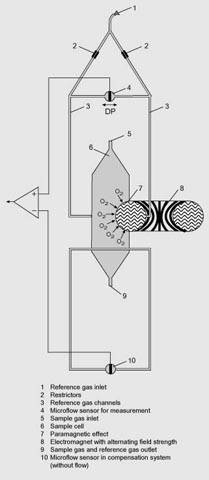 OXYMAT 6, mode of operation Essential characteristics
ULTRAMAT channel
OXYMAT channel
Reference gases
Table 1 Reference gases for OXYMAT 6 channel Correction of zero error / Cross interferences (OXYMAT channel)
Table 2 Zero error due to diamagnetism or paramagnetism of residual gases with nitrogen as the reference gas at 60 °C and 1000 hPa absolute (according to IEC 1207/3) Conversion to other temperatures: The zero errors mentionned in Table 2 must be multiplied with a correction factor (k):
(all diamagnetic gases have a negative zero error).
| |||||||||||||||||||||||||||||||||||||||||||||||||||||||||||||||||||||||||||||||||||||||||||||||||||||||||||||||||||||||||||||||||||||||||