Общее - CALOMAT 6
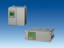 The CALOMAT 6 gas analyzer is primarily used for quantitative determination of H2 or He in binary or quasi-binary gas mixtures. Concentrations of other gases can also be measured if their thermal conductivities differ significantly from the residual gases like Ar, CO2, CH4, NH3.  19” unit and field unit
| ||||||||||||||||||||||||||||||||||||||||||||||||||||||||||||
Особенности
| ||||||||||||||||||||||||||||||||||||||||||||||||||||||||||||
Область применения
Special applicationsBesides the standard combinations, special applications are available on request (e.g. higher sample gas pressure up to 2000 hPa absolute). | ||||||||||||||||||||||||||||||||||||||||||||||||||||||||||||
Дизайн19“ unit
Field unit
Display and control panel
Inputs and outputs
Communication
Options
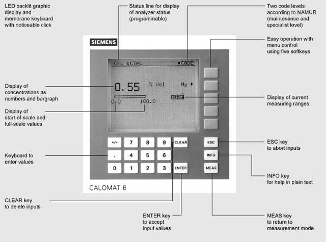 CALOMAT 6, membrane keyboard and graphic display Versions – Wetted parts
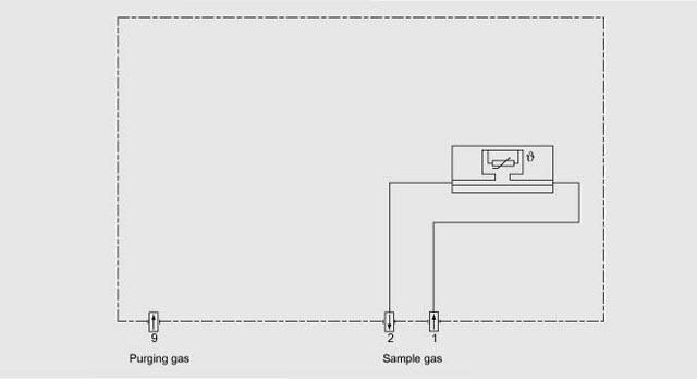 CALOMAT 6, 19“ unit, gas path 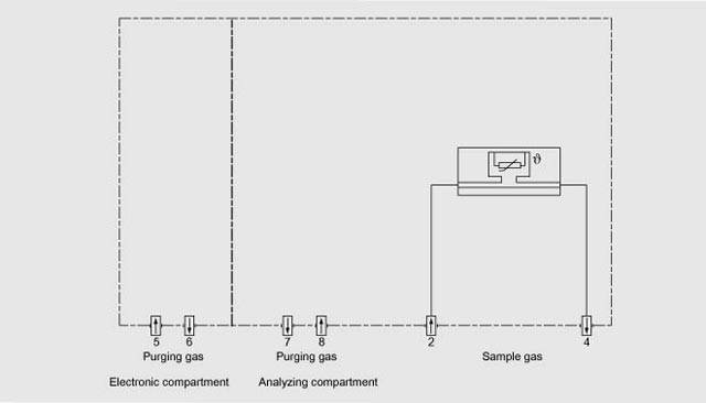 CALOMAT 6, field unit, gas path | ||||||||||||||||||||||||||||||||||||||||||||||||||||||||||||
ФункцииMode of operationThe measuring principle is based on the different thermal conductivity of gases. The CALOMAT 6 sensor is a micromechanical-made Si chip with a measuring membrane and thin-film resistors. The resistors are adjusted on a constant temperature. This requires an current intensity depending on the sample gas thermal conductivity. Further this „coarse value“ is electronically processed and used to calculate the gas concentration. The sensor is located in a thermostatically-controlled stainless steel enclosure in order to prevent influences of ambient temperature changes. To prevent the influences by the sample gas flow changes, the sensor is not placed in the main flow. Note The sample gas needs to be free of dust. Condensate (dew point of sample gas < ambient temperature) in the cells must be avoided. That is why the most measuring tasks require an appropriate gas preparation. 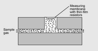 CALOMAT 6, mode of operation Special characteristics
SpansThe smallest and largest spans which are possible depend on the measured component (type of gas) as well as the respective application. The smallest possible spans listed below refer to N2 as the residual gas. With other gases which have a larger/smaller thermal conductivity than N2, the smallest possible span is also larger/smaller.
Influence of interfering gasesKnowledge of the sample gas composition is necessary to determine the influence of residual gases with several interfering components. The following table lists the zero offsets expressed in % H2 resulting from 10% residual gas (interfering gas) in each case.
For residual gas concentrations differing from 10%, the correspondant multiple of the table value gives an acceptable approximation. This is valid for for residual gas concentrations up to 25% (dependent on gas type). The thermal conductivity of most gas mixtures has a non-linear response. Even ambiguous results, such as e.g. with NH3/N2 mixtures, can occur within a specific concentration range. In addition to a zero offset, it should also be noted that the gradient of the characteristic is influenced by the residual gas. However, this effect is negligible for most gases. In case of correction of the influence of interfering gases with additional analyzers (ULTRAMAT 6/ULTRAMAT 23), the resulting measuring error can – depending on the application – amount up to 5% of the smallest measuring range of the application. Example interfering gas correctionSpecification of the interface cable
Bus terminating resistorsThe pin 3-7 and 8-9 of the first and last connector of a bus cable have to be bridged (see figure). Note It is advisable to install a repeater on the device side in case of a cable length increasing 500 m or of high interferences. Up to four components can be corrected via ELAN bus, a cross correction can be effected for up to two components via analog inlet. 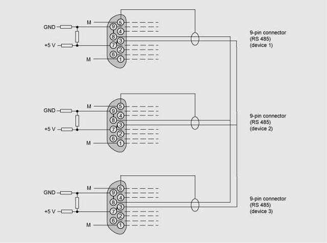 Bus cable with connector assignments | ||||||||||||||||||||||||||||||||||||||||||||||||||||||||||||