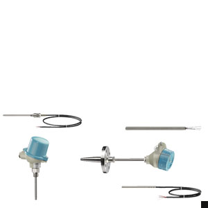
 ENG: SITRANS TS temperature sensors
 Photo Product Family
Temperature sensors of the SITRANS TS product family are used to measure temperatures in industrial equipment.
Siemens offers the following temperature sensors:
- SITRANS TS100
- general use
- Compact design with connection cable
- SITRANS TS200
- general use
- Compact design with plug/non-flexible wire ends
- SITRANS TS500
- general use
- modular design with connection head and protective tube
Особенности
ENG: SITRANS TS temperature sensors The modular design makes it possible to customize the temperature sensor for most applications, while still being able to use many standardized individual components.
Область применения
ENG: SITRANS TS temperature sensors Depending on the specification, sensors can be combined with different connection heads, neck tubes and process connections. As a result, the sensors can be used in a large number of technical applications in the following industries:
- Chemical industry
- Petrochemical industry
- Power engineering
- Basic material industry
- Pharmaceutical industry
- Biotechnology
- Food manufacturing
SITRANS TS100 and SITRANS TS200
Temperature sensors of the SITRANS TS100 series come with different electrical connection options (e.g. plug, soldered connections, connection cables)
The SITRANS TS200 series features a compact design. Both temperature sensors are suitable for the following:
- Measurements of temperatures of solids, where additional protective tubes are not required for replacements done during ongoing operations, e.g. bearing block temperature.
- Measurements which are particularly critical with regard to response times. The advantages offered by an additional protective tube are purposely omitted.
- Measuring points which can be easily converted or which must be able to change locations.
- Surface temperature measurements: The temperature sensor is used in conjunction with a surface connection piece.
- Cost-effective transport: The mineral-insulated design of the sensors
- allows for economically feasible transport even at large lengths. Starting with a length of 1 m, sensors are supplied in rolls.
SITRANS TS500 Temperature sensors as a module system
Due to their modular design, temperature sensors of the SITRANS TS500 series are well suited to a large number of applications.
The replaceable measuring insert makes it possible to conduct maintenance work even during ongoing operations. These devices are used particularly frequently in pipelines and tanks the following industries:
- Power stations
- Chemical industry
- Petrochemical industry
- General process engineering
- Water, waste water
Дизайн
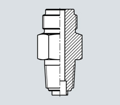
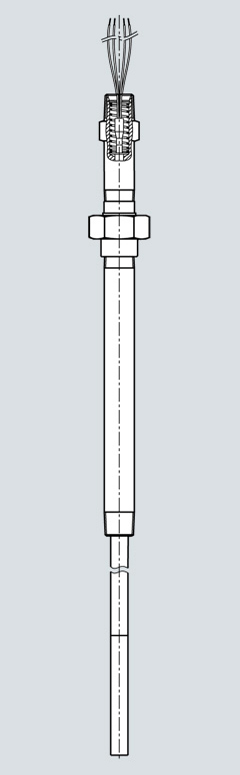
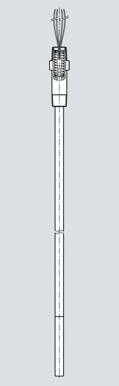
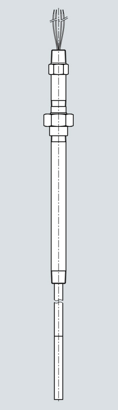
ENG: SITRANS TS temperature sensors SITRANS TS100 7MC711xx
The following image illustrates the available designs for SITRANS TS100 temperature sensors:
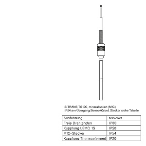
SITRANS TS100 cable temperature sensor, sensor, plastic-sheathed cable design (MIC)
The following types of process connections can be implemented:
- Compression joint
- Spring-mounted compression joint
- Soldering nipple
- Direct soldering/welding in
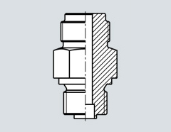
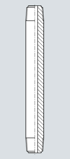
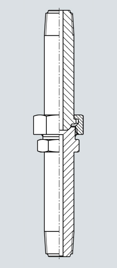
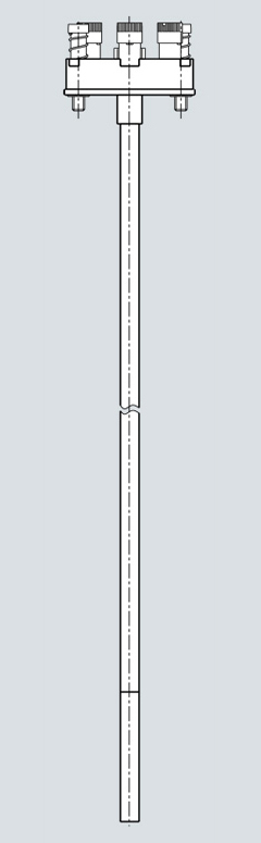
SITRANS TS200 7MC712xx
The following image illustrates the available designs for SITRANS TS200 temperature sensors:
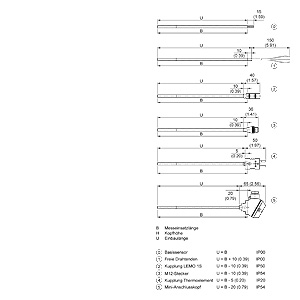
SITRANS TS basic sensor
The following types of process connections can be implemented:
- Compression joint
- Spring-mounted compression joint
- Soldering nipple
- Direct soldering/welding in
SITRANS TS500 7MC75xx
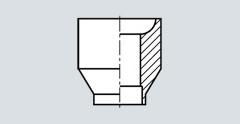
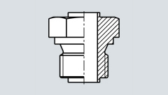
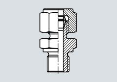
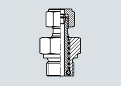
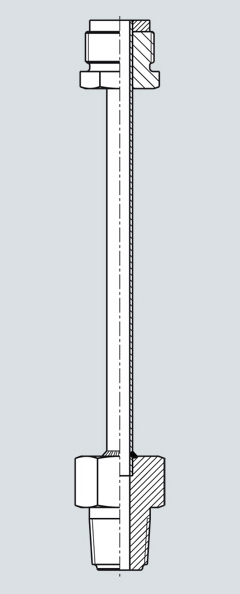
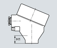
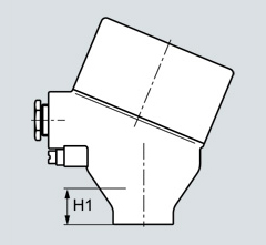
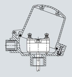
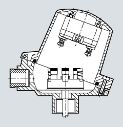
The following image illustrates the available designs for SITRANS TS500 temperature sensors:
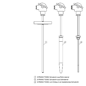
SITRANS TS500
The temperature sensors of the SITRANS TS500 series are available in three different designs:
| Version | Description | Application | Process connection |
|---|---|---|---|
| 1 |
| Minimal to medium process requirements |
|
| 2 |
| Medium to highest process requirements |
|
| 3 |
| Process requirements dependent on protective sleeve design | Screwed into existing protective sleeve. |
Функции
ENG: SITRANS TS temperature sensors A complete measuring point consists of a measuring insert which contains the basic sensors, the protective fitting and an optional measurement value processor (transmitter).
The basic sensors are:
- Resistance thermometers: Temperature measurement is based on the temperature dependency of the installed measuring resistor.
- Thermocouples: Temperature measurement is based on the Seebeck effect. A thermocouple which subjected to a temperature drop produces thermoelectric voltage that can be measured.
Transmitters:
The optional Siemens transmitters assume the following functions:
- Optimum measurement processing
- Strengthen weak sensor signals directly on site.
- Transmit standardized signals
- Protect against electromagnetic interspersion
- Option to conduct measuring point diagnostics.
Конфигурация
ENG: SITRANS TS temperature sensors Configuration
Components: Process connections
This catalog is limited to the standard versions. Special versions are available on request.
Welding
A welded protective tube provides a permanent, secure and highly resilient process connection, assuming a respective welding quality.
It is not possible to accidentally open the ... Additional gaskets are not required. If the pipe is not thick enough to ensure a secure welding connection, the appropriate weldable sockets are used.
Weldable sockets
Thread
Type of installation: Screw socket
Screw sockets of different thread types and sizes are firmly welded to the protective tube.
Screw socket
Type of installation: Compression joints
Compression joints are available as accessories. They fit with the diameter of the protective tube and provide for flexible installation. The mounting length can be selected on site. When installed correctly, compression joints are well suited for low and medium pressure.
The difference between a normal and spring-mounted design is as follows:
In the case of spring-mounted compression joints, the sensor is pressed against the measured object or the floor of the protective tube, thus achieving particularly strong heat contact.
Compression joint
Spring-mounted compression joint
Thread type: Cylindrical thread
Cylindrical threads do not seal in the thread but due to an additional sealing face or seal. For example, threads with the short form "G" (as per ISO 228) feature a threat type with a defined screw gauge.
Cylindrical thread
The male threads of our G½ screw sockets fit with both female G½ as well as Rp½ threads.
Thread type: Tapered thread
Tapered threads are different in that they seal metallically in the thread. For example, the American "NPT". Differently from the cylindrical threads, tapered threads such as the American "NPT" seal metallically in the thread itself. The relevant length information in the catalog refers to the "torque point" of the thread, which cannot be precisely defined due to standardized tolerance levels. However, the spring unit of the measuring insert compensates for the differences in length.
NPT thread
Flanges
The different properties of the flanges are as follows:
- Standard series EN 1092, ASME 16.5,..
- Nominal pressure
- Nominal diameter
- Sealing face
This information is also stamped into the flange, along with the material code and batch number for "3.1 Material".st
Industry-specific process connections
Special process connections have become popular in different industries. For example, hygiene technology: clamp-on connections, milk pipe unions and others.
Components: Protective tube
Protective tubes or sleeves fulfill two basic functions:
- they protect the measuring insert from aggressive media
- they make it possible to replace units during ongoing operations
This catalog is limited to the standard versions. Special versions are available on request. The large number of available types can be classified as follows:
- Protective tubes made of piping materialProtective tubes made of piping material are also described as "welded" or "multi-part" protective tubes. They are suitable for low to medium process loads and can be manufactured on a cost-effective basis. Versions :
- Form 2N similar to DIN 43772with straight tip and shortest possible extension lengthnon-alignable connection head
- Form 2 as per DIN 43772with straight tip and extensionalignable connection head
- Form 2: with process connectionForm 2G: Threaded connectionForm 2F: Flange connection
- Form 3 as per DIN 43772Design with tapered tip and extensionalignable connection headFor these protective tubes, the protective tube tip is tapered by hammering. This results in an excellent fit with the measuring insert and very good response times. Analogous to forms 2, versions 3/3G/3F are also available for 3
- Protective tubes made of solid materialsWhere process loads are too great, or where a protective tube cannot have a welded seam, deep hole drilled protective sleeves made of solid materials are used. Form 4 protective tubes (as per DIN 43772) are very popular in this area.
The following table shows the dimensions of the different protective tubes.
| Tip | Process connection | |||
|---|---|---|---|---|
| ∅ Inner [mm (inch)] | ∅ Outer [mm (inch)] | ∅ Inner [mm (inch)] | ∅ Outer [mm (inch)] | |
| Protective tube type, design | D1 | D2 | D3 | D4 |
| 2N/2/2G/2F, pipe | 7 | 9 | 7 | 9 |
| 2/2G/2F, pipe | 7 | 12 | 7 | 12 |
| 3/3G/3F, pipe | 6 + 0,1, 0,05 | 9 | 7 | 12 |
| 4/4F, Full | 7 | 12,5 | 7 | 24 |
| 4/4F, fast response, full | 3,5 | 9 | 3,5 | 18 |
Components: Extension
The extension is the section from the lower edge of the connection head to the fixed point of the process connection or protective tube. There are a variety of terms for this components, e.g. neck tube. For this reason the term extension has been selected as a standardized term for the different designs. Function is the deciding factor:
- Thermal decoupling of connection head from process temperature
- Installation of connection head over existing insulation
- Simple standardization of measuring inserts: In general, the length of the extension may be freely selected. However, when using standardized mounting lengths, the option "Extension as per DIN 43 772" is recommended. This ensures that measuring inserts which are quickly available can be used. In the case of special lengths, it is possible to standardize the measuring insert length through a clever combination with the respective special extension length. This allows customers to optimize their costs in purchasing and logistics.
- In the case of American-designed sensors, the extension also takes the spring load of the measuring unit.
- Depending on the design, the extension can also be used to achieve an alignment of the connection head.
- The form of the extension depends on the form of the protective tube:
- Protective tube made of piping material The extension and protective tube usually consist of one continuous tube. The process connection is welded on. (= one-piece protective fitting).
- Protective tubes made of solid materials Extension and protective tube consist of two components which are welded together. The process connection is attached to the protective tube (= multi-piece protective fitting).
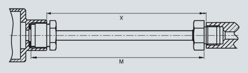
| Protective tube type | X [mm (inch)] | M[mm] (inch) | Divisible |
|---|---|---|---|
| 2G | 129 (5.08) | 145 (5.71) | No |
| 2F | 64 (2.52) | 80 (3.15) | No |
| 3G | 131 (5.19) | 147 (5.79) | No |
| 3F | 66 (2.60) | 82 (3.23) | No |
| 4 (only L=110) | 139 (5.47) | 155 (6.10) | Yes |
| 4 (others) | 149 (5.87) | 165 (6.50) | Yes |
Extensions as per DIN 43772
Versions
With regard to their function, extensions can be classified into two types:
- Alignable/non-alignable Ability to align connection head to the desired direction
- Integrated measuring insert spring load In the case of American-type sensors, the spring load of the measuring insert is integrated into the extension. Measuring insert and extension form one unit.
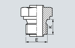
| alignable cylindrical | alignable tapered | without neck tube without thread |
 |  |  |
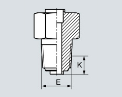
| non-alignable cylindrical | non-alignable tapered | non-alignable Nipple |
 |  |  |
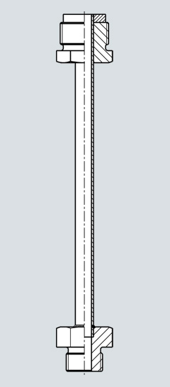
| alignable Nipple-Union-Nipple | alignable Nipple-Union-Nipple spring load | non-alignable Nipple-Union-Nipple spring load |
 |  |  |
Versions
Components: Connection head
Connection head
the connection head protects the connection department. The connection head features sufficient room for mounting a clamping base or transmitter.
Different connection heads are used depending on the application and preference:
| Connection head | Type/Material | Designation | Degree of protection | Transmitter installation | Connection height | Explosion protection optional |
|---|---|---|---|---|---|---|
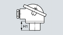 | BA0: Aluminum | Flange lid | IP54 | Measuring insert | 25 mm (0.98 inch) | Ex i |
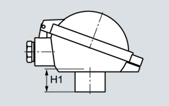 | BB0: Aluminum | Hinged cover low | IP 65 | Measuring insert | 25 mm (0.98 inch) | Ex i |
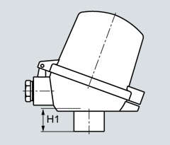 | BC0: Aluminum BC0: Plastic | Hinged cover high | IP 65 | Measuring insert and/or hinged cover | 25 mm (0.98 inch) | Ex i |
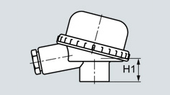 | BM0: Plastic | Screw cover | IP 65 | Measuring insert | 25 mm (0.98 inch) | Ex i |
 | AG0: Aluminum AU0: Stainless steel | Screw cover, heavy-duty | IP 68 | Measuring insert | 41 mm (1.61 inch) | Ex i, Ex d |
 | AH0: Aluminum AV0: Stainless steel | Screw cover, sight glass, heavy-duty | IP 68 | Measuring insert | 41 mm (1.61 inch) | Ex i, Ex d |
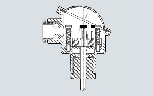
Components: Measuring insert
Measuring insert
The measuring insert of the temperature sensor is built into the protective fitting (protective tube, extension and connection head). The basic sensor is located in the measuring insert, where it is protected. The spring load of the Siemens measuring inserts provide good thermal contact with the floor of the protective tube, and vibration resistance is significantly increased. Only highly resistant mineral-insultaed cables (MIC or plastic-sheathed) are used for the electrical connection between the basic sensor and connection head. The highly compacted magnesium oxide insulation achieves excellent vibration resistance. The following measuring insert designs are the most popular on the world market:
 |  |
| European type | American type |
European type
European type measuring inserts can be replaced without having to dismantle the connection head. The springs are located either on the transmitter or the terminal block. This makes it possible to achieve a 8 to 10 mm spring range. Instead of a ceramic head, you can also mount a SITRANS-TH transmitter directly on the blank of the measuring insert.
American type
American-type measuring inserts feature a large spring range. These measuring inserts are ideal for use with NPT threads that feature high tolerances. In this configuration, the extension function is partially or fully integrated (nipple-union-nipple). Moreover it is also possible to directly attach field devices, e.g. SITRANS-TF.
Components: Transmitters
SITRANS-TH head transmitters process weak non-linear sensor signals and transmit a stable and temperature-linear standard signal, thereby minimizing sensor signal disruptions.
The transmitters permanently monitor the temperature sensors and transmit diagnostic data to superordinate systems.
Because of the low energy feed of the SITRANS-TH head transmitters, self-heating of the temperature sensors can be maintained at minimal levels.
The electrical isolation and integrated cold junction ensure that temperature sensors with thermocouples provide reliable measurements at a low cost.
SITRANS-TH product family
- TH100 - the basic device
- Output 4..20mA
- for PT100
- can be configured using simple software
- TH200 - the universal device
- Output 4..20mA
- Resistance thermometer, thermocouples
- can be configured using simple software
- TH300 - HART universal
- Output 4..20mA/HART
- Resistance thermometer, thermocouples
- HART conforming
- Diagnostic functions
- TH400 - Fieldbus PA and FF
- Output PROFIBUS PA or FOUNDATION Fieldbus
- Resistance thermometer, thermocouples
- Diagnostics
Installation types
All SITRANS-TH transmitters can be installed in type B connection heads. The following installation forms are used:
- Measuring insert installationOur standard version offers the following advantages
- Small vibrating masses and compact design
- Measuring insert-transmitter unit can be replaced quickly
Installation of measuring insert
- Hinged cover installation
- Standard for head type BC0 and BP0
- Advantage: Measuring insert and transmitter can be repaired/maintained separately (recalibration).
Hinged cover installation
Measuring technology: Basic sensors
The diverse application spectrum for industrial temperature measuring technology requires different sensor technologies.
Resistance thermometer
The Pt100 resistance thermometers in this catalog correspond with IEC 751/EN 60 751.
Basic sensors made of other basic materials, with different basic values or different underlying standards are available on request. Resistance thermometers can be classified as follows
- Basic design The sensor element is built with thin layer technology. The resistance material is applied in the form of a thin layer on a ceramic carrier material.
- Versions featuring increased vibration resistance In addition to the basic design: Measures to improve vibration resistance.
- Versions with expanded measuring range Elements in wire-wound design. The wire winding is embedded in a ceramic body.
Thermocouples
The thermocouples in this catalog correspond with IEC 584/EN 60 584.
Other thermocouples based on other thermo pairs or underlying standards are available upon request.
The most common ignoble thermocouples are:
- Type N (NiCrSi-NiSi) high degree of stability even in upper temperature range.
- Type K (NiCr-Ni) more stable than type J, but drifts in upper range.
- Type J (Fe-CuNi) narrow application band.
Measuring technology: Measuring range
The measuring area describes the temperature limits within which the thermometer can be used in a way that is meaningful for measurement purposes. Depending on the loads present and the desired accuracy levels, the actual application range for the thermometer may be smaller.
| Resistance thermometer | |
|---|---|
| Basic version and increased vibration resistance | -50 ... 400 °C (-58 ... 752 °F) |
| Expanded measuring range | -200 ... 600 °C (-328 ... 1112 °F) |
| Thermocouple | |
|---|---|
| Type N | -40 ... 1100 °C (-40 ... 2112 °F) |
| Type K | -40 ... 1000 °C (-40 ... 1132 °F) |
| Type J | -40 ... 750 °C (-40 ... 1382 °F) |
Measuring technology: Measuring accuracy
Resistance thermometer
The tolerance classes of the resistance thermometers correspond with IEC 751/EN 60751:
| tolerance | Δt |
|---|---|
| Basic accuracy, Class B | ±(0.30 °C+0.0050|t|) |
| Increased accuracy, Class A | ±(0.15 °C+0.0020|t|) |
| High degree of accuracy, Class 1/3 B | ±(0.10 °C+0.0017|t|) |
The following tables provide an overview of the scope of these tolerances. If you exceed the specified limits with a resistance thermometer, the values of the next lower accuracy class apply:
| Resistance thermometerBasic version | |
|---|---|
| tolerance | Range |
| Basic accuracy, Class B | -50 °C ... 400 °C (-58 ... 752 °F) |
| Increased accuracy, Class A | -50°C..300°C (-58 ... 572 °F) |
| High degree of accuracyClass AA (1/3 B) | 0°C..150°C (32 ... 302 °F) |
| Resistance thermometerIncreased vibration resistance | |
|---|---|
| tolerance | Range |
| Basic accuracy, Class B | -50 °C ... 400 °C (-58 ... 752 °F) |
| Increased accuracy, Class A | -50°C..300°C (-58 ... 572 °F) |
| High degree of accuracyClass AA (1/3 B) | 0°C..150°C (32 ... 302 °F) |
| Resistance thermometerExpanded measuring range | |
|---|---|
| tolerance | Range |
| Basic accuracy, Class B | -196 °C ... 600 °C (392 ... 1112 °F) |
| Increased accuracy, Class A | -196 °C ... 600 °C (392 ... 1112 °F) |
Depending on the thermal and mechanical loads at the site, the actual application range of the thermometer may be smaller.
Thermocouples
The tolerance classes of the thermocouples correspond with IEC 584/EN 60584:
Catalog versions
| Type | Basic accuracy, Class 2 | Increased accuracy, Class 1 |
|---|---|---|
| N | -40 °C ... 333 °C±2,5 °C (-40 °F ... 631.4 °F±4.5 °F)333 °C ... 1200 °C±0,0075 x |t| (631.4 °F ... 2192 °F±0.0075 x |t|) | -40 °C ... 375 °C±2,5 °C (-40 °F ... 707 °F±2.7 °F)375 °C ... 1000 °C±0,004 x |t| (707 °F ... 1832 °F±0.004 x |t|) |
| K | -40 °C ... 333 °C±2,5 °C (-40 °F ... 631.4 °F±4.5 °F)333 °C ... 1200 °C±0,0075 x |t| (631.4 °F ... 2192 °F±0.0075 x |t|) | -40 °C ... 375 °C±2,5 °C (-40 °F ... 707 °F±2.7 °F)375 °C ... 1000 °C±0,004 x |t| (707 °F ... 1832 °F±0.004 x |t|) |
| J | -40 °C ... 333 °C±2,5 °C (-40 °F ... 631.4 °F±4.5 °F)333 °C ... 750 °C±0,0075 x |t| (631.4 °F ... 1382 °F±0.0075 x |t|) | -40 °C ... 375 °C±2,5 °C(-40 °F ... 707 °F±4.5 °F)375 °C ... 750 °C±0,004 x |t| (707 °F ... 1382 °F±0.004 x |t|) |
Other thermocouples, ignoble
| Type | Basic accuracy, Class 2 | Increased accuracy, Class 1 |
|---|---|---|
| T | -40 °C ... 133 °C±1 °C(-40 °F ... 271.4 °F±1.0 °F)133 °C ... 350 °C±0,0075 x |t| (271.4 °F ... 662 °F±0.0075 x |t|) | -40 °C ... 125 °C±0,5 °C(-40 °F ... 257 °F±0.9 °F)125 °C ... 350 °C±0,004 x |t| (257 °F ... 662 °F±0.004 x |t|) |
| E | -40 °C ... 333 °C±2,5 °C (-40 °F ... 631.4 °F±4.5 °F)333 °C ... 900 °C±0,0075 x |t| (631.4 °F ... 1652 °F±0.0075 x |t|) | -40 °C ... 375 °C±1,5 °C(-40 °F ... 707 °F±2.7 °F)375 °C ... 800 °C±0,004 x |t| (707 °F ... 1472 °F±0.004 x |t|) |
Other thermocouples, noble
| Type | Basic accuracy, Class 2 | Increased accuracy, Class 1 |
|---|---|---|
| R and S | 0 °C ... 600 °C±1,5 °C (32 °F ... 1112 °F±2.7 °F)600 °C ... 1600 °C±0,0025 x |t| (1112 °F ... 2912 °F±0.0025 x |t|) | 0 °C ... 1100 °C±1 °C(32 °F ... 2012 °F±1.8 °F)1100 °C ... 1600 °C±[1 + 0,003 (t - 1100)] °C (2112 °F ... 2912 °F±[1.8 + 0.003 (t - 212)] °F) |
| B | 600 °C ... 1700 °C±0,0025 x |t|(1112 °F ... 3092 °F±0.0025 x |t|) |
Measuring technology: Response times
Response time describes the speed of the measurement system in the case of a temperature change, and is typically indicated as T0.5 or T0.9. The values indicate the time in which a measured value has increased to 50% or 90% of the actual temperature increase.
The main variables which affect response time are as follows:
- Protective tube geometry Ideally: as little material as possible at tip, use of conductive material
- Thermal connection of measuring insert to protective tube:Because of design changes implemented for the measuring insert (small gap width, spring system), Siemens measuring inserts feature very good response behavior. Because of the good fit, additional contact materials are not usually required except in certain applications e.g. attachment of a surface sensor.
- Size of temperature increase
- Medium and flow rate
Resistance thermometer
Typical values as per EN 60751 in water at 0.4m/s can be found in the following table.
| Protective tube form | Diameter [mm] | T0.5 | T0.9 |
|---|---|---|---|
| None | 6 mm (0.24 inch) 3 mm (0.12 inch) | 3,9 1 | 11,4 3,5 |
| straight (2) | 9 mm (0.35 inch) 12 mm (0.47 inch) | 30 23 | 96 69 |
| Tapered (3) | 12 mm (0.47 inch) | 10 | 24 |
| Solid material (4)U=65 | 24 mm (0.95 inch) | 27 | 77 |
| Solid material (4)]U=125 | 24 mm (0.95 inch) | 30 | 85 |
| Solid material (4)U=65 | 18 mm (0.71 inch) | 19 | 52 |
Thermocouples
Typical values as per EN 60751 in water at 0.4m/s can be found in the following table.
| Protective tube form | Diameter [mm] | T0.5 | T0.9 |
|---|---|---|---|
| None | 6 mm (0.24 inch) 3 mm (0.12 inch) | 2 0,5 | 4 1 |
| straight (2) | 9 mm (0.35 inch) 12 mm (0.47 inch) | 20 19 | 63 66 |
| Tapered (3) | 12 mm (0.47 inch) | 7 | 22 |
| Solid material (4)U=65 | 24 mm (0.95 inch) | 22 | 73 |
| Solid material (4)]U=125 | 24 mm (0.95 inch) | 20 | 53 |
| Solid material (4)U=65 | 18 mm (0.71 inch) | 12 | 41 |
Measuring technology: Mounting depth
Measuring insert
| Type | Temperature-sensitive length (TSL) [mm] | Non-bendable length [mm] |
|---|---|---|
| Basic | 7 mm (0.28 inch) | 30 mm (1.82 inch) |
| Increased vibration resistance | 7 mm (0.28 inch) | 30 mm (1.82 inch) |
| Expanded measuring range | 50 mm (1.97 inch) | 60 mm (2.36 inch) |
| Thermocouple | 3 mm (0.12 inch) | 3 mm (0.12 inch) |
Contact with media
Ambient conditions (temperature/weather/insulation) and the size of the protective tube, process connection and piping result in so-called "heat transmission errors".
To prevent such an error, the submersion depth and diameter of the protective tube tip are defined. The temperature-sensitive length (TSL) of the protective tube must also be taken into account.
- WaterSubmersion depth ≥ TSL + 5 x Ø of protective tube
- AirSubmersion depth ≥ TSL + 10..15 x Ø of protective tube
- Recommendations
- Select largest possible submersion depth
- Select measuring location with higher flow velocity
- Insulate outer components of thermometer
- Smallest possible surface for outer components
- Installation in pipe bends, left
- Direct measurements without additional protective tube if no suitable solution can be found using other measures.
Measuring technology: Connection types
In the case of resistance thermometers, the type of sensor connection directly affects the level of accuracy:
Two-wire system
The resistance of sensor lines are included in the measurement result as an error. Adjustments are recommended in this case.
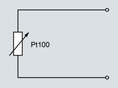
PT100 2-wire system
Three-wire system
Line resistance is not included in the measurement result. Requirements: all terminal and line resistances (corrosion) are at the same level, and terminals are at the same temperature level.

PT100 three-wire system
Four-wire system
Line resistance is not included in the measurement result. This type of connection is the most secure and most accurate.

PT100 four-wire system
Siemens measuring inserts can be used to implement all types of connections for 1 x Pt100 devices. In the case of 2 x Pt100 versions, two- and three-wire systems are also possible. For measurement-related reasons, we always recommend a 1 x four-wire or 2 x 3-wire connection.
Temperature influence
At the connection head
| without transmitter | with transmitter | |
|---|---|---|
| Aluminum or stainless steel | -40 ... 150 °C (-40 ... 302 °F) | -40 ... 85 °C(-40 ... 185 °F) |
| Plastic | -40 ... 85 °C(-40 ... 185 °F) | -40 ... 85 °C(-40 ... 185 °F) |
Influence of extension
The illustration below assists you in selecting the right length for the neck tube.
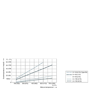
length of neck tube, effect on temperature
Please note that guidance values may change due to local conditions. Please consider these potential changes particularly with respect to explosion protection.
Also note that the accuracy of the transmitter also depends on the temperature in the connection head.
Process connection/Protective tube
When selecting a process connection, process parameters of a certain technology can be considered along with regional, standard-based and customer-specific requirements. The range of products includes a broad selection of standard connections. Additional products are available on request.
In the case of redesigned or newly designed facilities, it is possible to achieve cost savings by implementing various measures:
- Use of standard lengths through clever selection of screw, weld or flange sockets
- Moveable compression joints
The temperature resistance of a material for process connections and protective tubes also limits the application area of the temperature sensor. The temperature range indicated on the type plate always refers to the measuring insert, not the material which comes into contact with media. Two aspects must be considered when assessing temperature stability:
- What maximum temperature may the material reach without a load?
- What is the behavior under load?
Process load
Because of the large variety of possible applications and variables, it is not possible to make general binding statements regarding the resilience of components which comes into contact with media. The load diagrams below can be used for common application areas. However, where operating conditions vary significantly, please contact our technical support team.
Possible variables affecting measuring accuracy:
| The process itself | Correction options |
|---|---|
| Temperature | Mounting lengths |
| Pressure | Protective tube type |
| Flow velocity | Material selection (incl. coating) |
| Viscosity | Suitable process connection |
| Vibration | Support against vibration |
| Corrosiveness | |
| Abrasion (e.g. carbon dust) |
Load diagrams
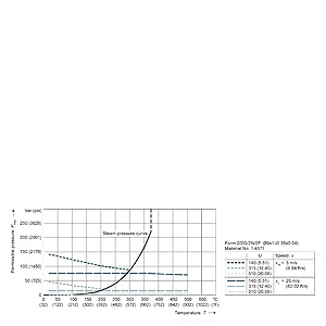
Protective tubes with Ø9.1 mm(0.36 inch) ,measurements in mm (inch)
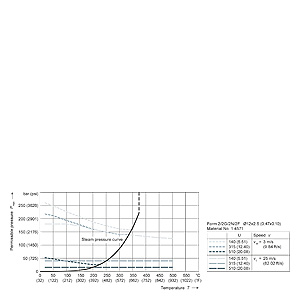
Protective tubes with Ø12 x 2.5 mm (0.47 X 0.10 inch), measurements in mm (inch)
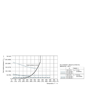
Protective tubes with Ø12 x 2.5 mm (0.47 X 0.10 inch), Ø14 x 2.5 mm (0.55 X 0.10 inch), measurements in mm (inch)
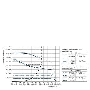
Protective tubes with Ø14 mm (0.95 inch), C= 65 mm (2.60 inch), measurements in mm (inch)
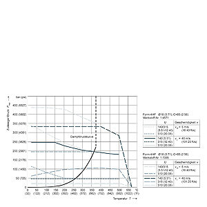
Protective tubes with Ø18 mm (0.71 in), C= 65 mm (2.60 inch), measurements in mm (inch)
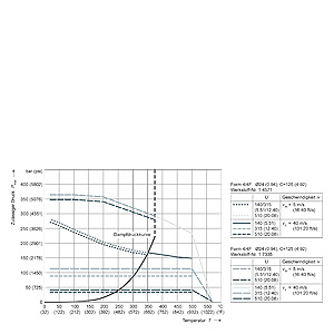
Protective tubes with Ø14 mm (0.95 inch), C= 4.92 in (4.92 in), measurements in mm (inch)
Protective tube calculation
Properly applied load diagrams will provide a sufficient degree of safety for the most common protective tube configurations.
However, there are cases in which operating conditions excessively deviate from standard parameters. In this case a customized protective tube calculation may be required.
Another reason for doing this calculation is the fact that flowing media can create turbulence at the tip of the protective tube under certain conditions. The protective tube will then vibrate and may even be destroyed if not configured correctly. This is the most common cause for breakdowns involving protective tubes.
SIEMENS offers the two recognized methods for calculating the protective tube:
- DIN/Dittrich method
- ASME/Murdock method This method also takes into account turbulence formation on a mathematical level.
Both methods provide a high degree of safety with regard to protective tube configuration, however, they do not provide a guarantee against breakdowns.
Materials
| Material descriptions/Standards comparison | Maximum temperature | Properties | Applications | |||
|---|---|---|---|---|---|---|
| Mat. No.: | AISI/Trade name: | EN 10028-2: | Description | |||
| 1.4404 | AISI 316 L | X2CrNiMo17-12-2 | Austenitic stainless steel | 600°C | good acid resistance, resistant against grain boundary corrosion | Chemical industry, waste treatment, paper and cellulose industry, food industry |
| 1.4571 | AISI 316 Ti | X6CrNiMoTi 17 12-2 | Austenitic stainless steel | 800°C | good acid resistance, resistant against grain boundary corrosion (supported by TI portion) | Chemical industry, textile industry, paper and cellulose industry, water supply, food and pharmaceuticals |
| 1.5415 | A 204 Gr.A | 16Mo3 | Carbon steel, high-alloy | 500°C | Resistant at higher temperatures, well suited for welding | Steam turbines, steam lines, water pipes |
| 1.7335 | A 182 F11 | 13CrMo4-5 | Carbon steel, high-alloy | 540°C | Resistant at higher temperatures, well suited for welding | Steam turbines, steam lines, water pipes |
| 1.4841 | SS 314 | X15CrNiSi25-20 | Austenitic heat-resistant stainless steel | 1150 °C | Resistant at high temperatures, also resistant against low-O2 and nitrogen-containing gases. | Flue gas, petrochemical industry, chemicals industry, power plants |
| 1.4762 | 446 | X10CrAl24 | Ferritic heat-resistant steel | 1150 °C | Resistant at high temperatures, in oxidizing and reducing sulphur-containing atmosphere | Chemical industry, power plants, steel industry, waste gas treatment |
| 2.4816 | Inconel 600 | NiCr15Fe | Nickel-Chrome alloy | 1150°C | Resistant at high temperatures, resistant against chlorine-induced cold crack corrosion | Chemical industry, petrochemical industry, food industry |
| 1.4876 | Incoloy 800 | X10NiCrAlTi32-21 | Austenitic heat-resistant stainless steel | 1100°C | Excellent resistance against oxidation and carbonization at high temperatures, good corrosion resistance | O&G industry, waste gas treatment, power plants (steam boiler, heat exchanger), applications using aggressive fluids |
| 2.4819 | Hastelloy C 276 | NiMo16Cr15W | Nickel-Chrome-Molybdenum alloy | 1100°C | Resistant at high temperatures, in oxidizing and reducing atmosphere, resistant against pitting and crevice corrosion, good corrosion resistance after welding | Chemicals industry, paper and cellulose industry, waste treatment, waste incinerators, emissions controls, shipbuilding and offshore industry |
| 2.4360 | Monel 400 | NiCu30Fe | Nickel-Copper alloy | 500°C | Excellent corrosion resistance, particularly against chlorine-induced cold crack corrosion | Chemical industry, offshore industry, nuclear technology, petrochemical industry |
Where cost-intensive materials are used with flange protective tubes, cost savings can be achieved by using a so-called flanged wheel. A thin disc of the material which comes into contact with media is applied prior to the flange (ordinary stainless steel).
Vibration resistance of measuring insert, cable sensor
Similar to the protective tube, the equipment also creates inner (Karman vortices) and outer vibration inducements which act on the measuring insert. For this reason, a special assembly of measurement elements is required. Other than a few exceptions for cable and compact thermometers, SIEMENS only produces sensors with a mineral-insulated plastic-sheathed cable. Together with precautions taken when installing the measuring element, the SIEMENS basic version already exceeds EN 60 751 by more than a factor of 3. Pursuant to the measurement methods of this standard, the following values are obtained (tip-tip):
- 10 g Basic version and expanded measuring range
- 60 g Increased vibration resistance and thermocouple
Bending ability of measuring insert / cable sensor
All SIEMENS measuring inserts are made with a mineral-insulated plastic-sheathed cable (MIC). The same applies to a portion of the cable and compact thermometer. In addition to the already described properties, another advantage of the plastic-sheathed cable is its bending ability. This makes it possible to install these thermometers even in difficult to access areas. Please ensure that you are not below the following bending radius:
| Ø MIC [mm] (inch) | Rmax = 4x Ø MIC [mm] (inch) |
|---|---|
| 3 (0.12) | 12 (0.48) |
| 6 (0.24) | 24 (0.95) |
Where a smaller bending radius is required due to installation conditions, subsequent testing of the insulation resistance is recommended.
Electrical stability
Insulation resistance
The insulation resistance between each measuring circuit and the fitting is tested at a voltage of 500 V DC at room temperature.
Riso ≥ 100 MΩ
Due to the property of the mineral-insulated cable, the insulation resistance decreases as temperature increases. Because of the special production method, it is however possible to achieve very good values even at high temperatures.
Line resistance
When connected to two-wire systems, the line resistance is included in the measurement result. The following rule of thumb can be used:
- ∅ Measuring insert 3 mm (0.12 inch) 5 Ω/m or 12.8 °C (55.04 °F)
- ∅ Measuring insert 6 mm (0.24 in) 2.8 Ω/m or 44.78 ℉ (44.78 ℉)
For this reason a connection to three- or four-wire systems is highly recommended.
Approvals
- ATEX intrinsically-safe PTB 08 ATEX ... X
- II 1/2 GD Ex ib, II 1 GD Ex ia
- ATEX pressure-resistant PTB 08 ATEX ... X
- II 1/2 GD Ex d
Pressure equipment directive:
This device is not covered by the pressure equipment directive; classification as per the pressure equipment directive:
(DGRL 97/23/EG), Directive 1/40; Section 1, Subsection 2.1.4
In addition, statutory, standards-based or operating specifications also require additional testing. The results are certified in certificates as per EN 10204:
- as per EN 10 204-2.1, order conformityCertificate in which SIEMENS confirms that the delivered products correspond with the requirements of the order, without indicating test results. The testing does not have to be carried out on the delivered devices.
- as per EN 10 204-3.1Certificate in which SIEMENS confirms that the delivered products meet the requirements set out in the order. Along with listing the test results. Testing is carried out by an organization which is independent of production. The acceptance test certificate 3.1 replaces 3.1.B of the previous edition.
- Material certificate for parts which come into contact with mediaThis certificate confirms the properties of the material and warrants traceability up to the melting batch.
- Pressure-resistantHydrostatic pressure test on protective tube as per customer specifications. Where operating pressure is not specified, testing is carried out using the nominal pressure of the process connection.
- Helium leak testThis test can be used to detect even the smallest leaks in protective tubes and welded seams.
- X-ray testing for measuring insertsBy conducting an X-ray test, welded connections can be tested for e.g. bubbles, insufficient weld penetration and other material defects.
- Surface tear testThe color penetration method can detect tears and other surface defects.
- Comparative text (calibration)The test object is measured in one temperature direction against a highly precise thermometer, and the measured values of test object and normal are documented. However, calibration requires the measuring insert to be of a certain minimum length.Measuring inserts can be calibrated together with the associated transmitter. Calibration values can be stored in the transmitter in order to increase the accuracy of the system.
- as per EN 10 204-3.2This acceptance certificate can be prepared on request, together with an acceptance representative of the ordering party or a representative indicated as per official requirements (e.g. TÜV) It confirms that the delivered products meet the requirements set out in the order; it also contains the test results.
Схема подключения
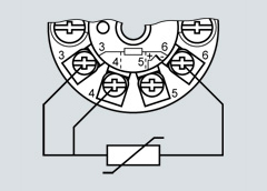
ENG: SITRANS TS temperature sensors Resistance thermometer
SIEMENS measuring inserts are generally designed as a four-wire system for simple PT100. This makes it possible to implement all of the aforementioned connection types.
Double PT100 measuring inserts are designed as a three-wire system; four-wire systems are available on request.

Circuit diagram 1xPT100-2W - 2xPT100-4W
Thermocouples
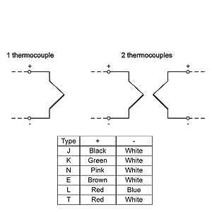
Circuit diagram for thermocouple
Where thermocouples are used, the use of head transmitters offers particular advantages: The cold junction is already integrated into the universal transmitter. There is no need for expensive thermo or extension leads. This also removes a number of possible error sources. The weak millivolt signal of the thermocouple is already converted into a stable and temperature-linear DC or bus signal on site. This drastically reduces the effects of electromagnetic factors on the measurement result.
If a head transmitter is not installed, the sensor feed line consists either of the appropriate thermo or extension leads. The thermo line is made from the thermo material of the relevant thermocouple, while the extension lead uses a cost-effective substitute material. The extension lead behaves similar to a thermo line at an electrical level, within a limited temperature range of up to 200°C.
A wide spectrum of color coding is available for thermocouples on an international level. This must be taken into account during the connecting process.
| Country | International/Germany | North America | UK/Czech Republic | ||||||
|---|---|---|---|---|---|---|---|---|---|
| Standard | Not intrinsically safe1) | Extension lead2) | BS 1843 | ||||||
| Jacket | + | - | Jacket | + | - | Jacket | + | - | |
| N | rs | rs | Ws | or | or | rt | or | or | bl |
| K | gn | gn | Ws | ge | ge | rt | rt | br | bl |
| J | sw | sw | Ws | sw | ws | rt | sw | ge | bl |
| T | br | br | Ws | bl | bl | rt | bl | ws | bl |
| E | vio | vio | Ws | vio | vio | rt | br | br | bl |
| R+S | or | or | Ws | sw | rt | gn | ws | bl | |
| B | gr | gr | Ws | gr | gr | rt | - | - | - |
1) With an intrinsically safe line as per IEC 584-3, the sheath is always blue.
2) For thermo lines as per ANSI MC96, the sheath is always blue.
| Country | Netherlands | Japan | France | ||||||
|---|---|---|---|---|---|---|---|---|---|
| Standard | DIN 43714 | ISC 1610-198 | NF C42-323 | ||||||
| Jacket | + | - | Jacket | + | - | Jacket | + | - | |
| N | - | - | - | - | - | - | - | - | - |
| K | gn | rt | gn | bl | rt | ws | vio | vio | ge |
| J | bl | rt | bl | ge | rt | ws | sw | sw | ge |
| T | br | rt | br | br | rt | ws | bl | bl | ge |
| E | sw | rt | sw | vio | rt | ws | or | or | ge |
| R+S | ws | rt | ws | sw | rt | ws | gn | gn | ge |
| B | gr | rt | gr | gr | rt | ws | - | - | - |
| Abbreviation for colors | ||||
|---|---|---|---|---|
| br: brown | gn: green | gr: gray | or: Orange | rs: pink |
| rt: Red | sw: black | vio: Violet | ws: white | |
Transmitters
Where SITRANS TH transmitters are used in the connection head of the temperature sensor, connection takes place according to the following pattern
Resistance thermometer
Thermocouples intern cold junction
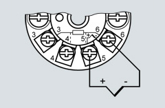
SITRANS TH100/TH200/TH300
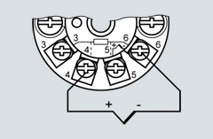
SITRANS TH400
In addition, our transmitters also allow for a large number of other possible connections (e.g. difference, average, two sensors). More information can be obtained at: http://www.siemens.com/temperature